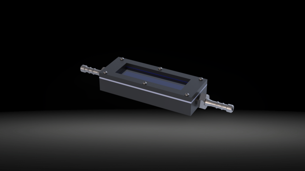
Here’s a small project I did for for a UMass Lowell Dept. of Chemistry professor. It’s a flow-through cell (liquid or gases) with a UV transparent window. Inside, the researcher places a standard microscope slide with some photo-active material on it that reacts with whatever is flowed through the cell. Chemical reactions are driven by exposure to the UV light. Kind of cool.
Made completely in-house. The body is printed in PETG, fittings in 316 stainless with a PTFE gasket under the cover. Some tapped holes, but no inserts.
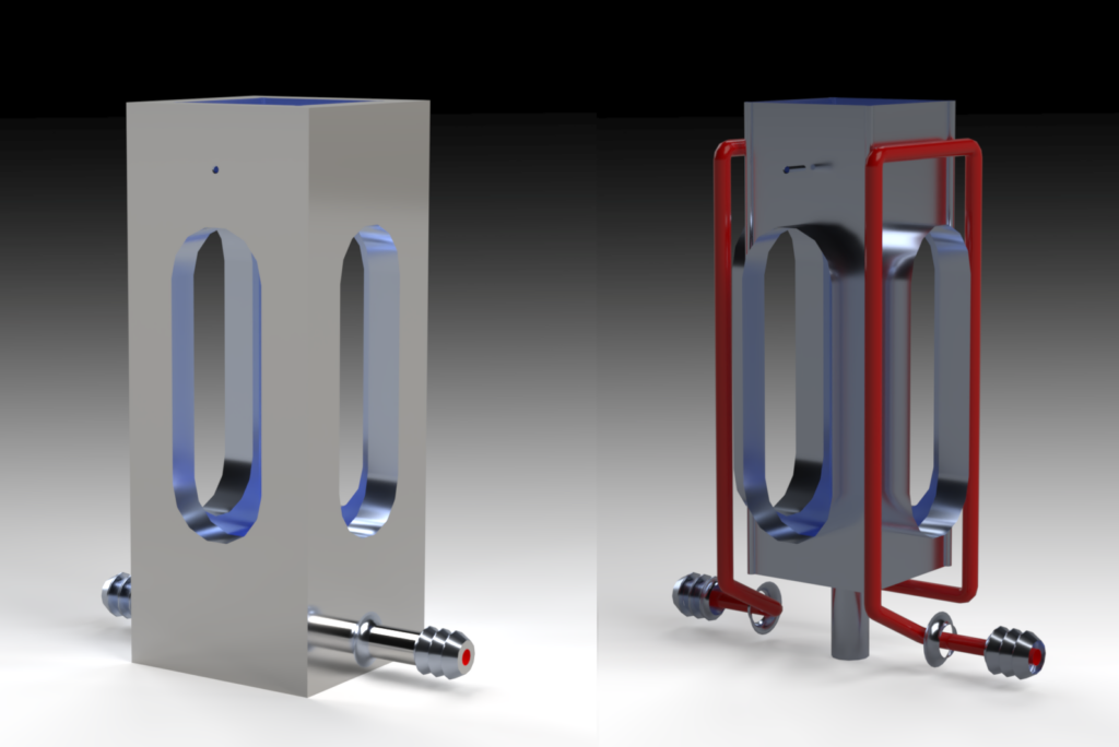
Here’s another small project for UMass Lowell’s Chemistry Department. It’s an all-metal cuvette holder with internal passages to allow a coolant to flow through. Hose connections were integrally printed. The idea is to control the temperature of a liquid sample in a quartz cuvette. It’s fabricated using AlSi10Mg Direct Metal Laser Sintering (AM) sent to a 3rd party for printing.Bijou Works LLC worked closely with the chemist/client to establish requirements and did all the Solidworks CAD, project management, working with the vendor, etc.
Below, on the left, you can see the finished cuvette holder, on the right is an “X-ray” view showing the internal passage in red.
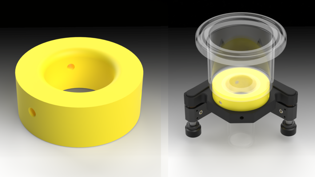
Sometimes it’s pretty simple. Here’s a 3D printed part in PETG I made for a researcher at Tufts, a physical chemist working with LN2 in a laser lab. She needed a spacer/insulator to hold a glass cell on a Thorlabs KM200 2″ mirror mount. The idea is to insulate the mirror mount from the very low temperature of the glass cell. Designed in Solidworks, sliced with PrusaSlicer, printed on a Prusa MINI+.
On left, below, is the spacer ring and on the right is the ring assembled on the KM200 with the glass cell in place so you can see how it was used.
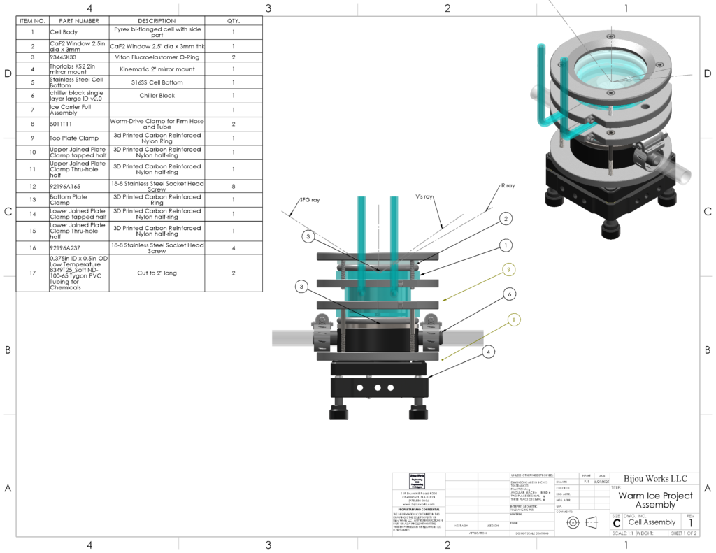
The Warm Ice Project. Something a little more complicated. Again for Tufts Chemistry, this optical cell conditions ice at about -20C. These researchers normally work at liquid Nitrogen temperatures (-196C), hence this is ‘warm’ ice.
It includes 3D printed parts using carbon reinforced plastics. In one case for strength and for another, for better thermal conductivity. At the base of the cell is a 3D printed heat exchanger with ethylene glycol/water coolant flowing through. Inside the cell, it’s more complicated with some SS parts to support and position a small sample of single-crystal ice.
Designed with Solidworks, sliced with Prusa Slicer, printed on a Prusa MINI+.
Meso-Fluidics? Is that a thing?
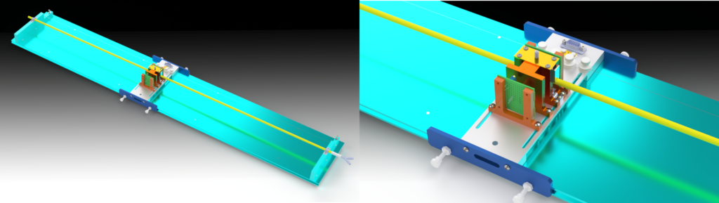
The whole 4′ long instrument, left. Closeup of the moving photometer, right. The quartz reaction tube is rendered in yellow to aid seeing.
Well, here’s a instrument I designed and built for a UMASS Lowell Physical chemist way back in about 2004. It’s still in use in the physical chemistry classroom. Designed using Solidworks, user interface in LabVIEW, some EE stuff, some optics, some spectroscopy. Kind of a fun project.
I called this instrument a ‘Continuous Flow Moving Photometer’. It’s used to study moderately fast (i.e. ~1s to completion) chemical reactions. It incorporates many principals from the science of micro-fluidics, but at a ‘meso’ scale. The flow channel is about 4mm diameter. But that’s small enough to demonstrate many microfluidics principles.
You can read more about it here:
Bisson, P.; Whitten, J. E. Studying Fast Reactions: Construction and Use of a Low-Cost Continuous-Flow Instrument. J. Chem. Educ. 2006, 83 (12), 1860–1863. https://doi.org/10.1021/ed083p1860.
Without a UI, it’s just a pile of parts on the bench.
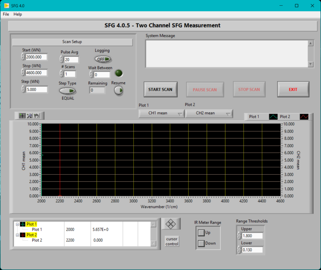
Most instruments also have a UI. LabVIEW is a very good development system for such a thing. It can acquire data, process it and issue commands and control to sub-components in the system. Not to mention put up a good looking graphical user interface.
Here’s the front panel of a complex system I wrote for a Tufts researcher. I call it “SFG 4”. Where SFG stands for Sum Frequency Generation, a laser based spectroscopy that gives vibrational spectra of surfaces.
This system controls multiple optical and electronic instruments on a large optical bench. It acquires raw data, processes and logs it, and displays it on the UI. It has an explicitly multi-threaded architecture using a messaging system for thread command, control, data communication.
Growing Single Crystal Ice. That’s easy, right?
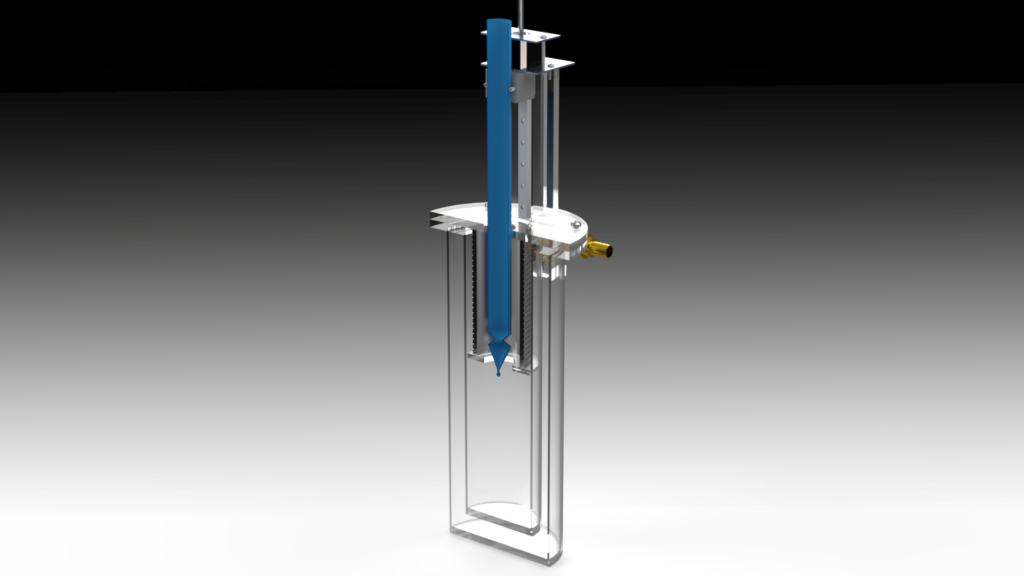
Err…nope! Back in the late 2000’s I helped develop this single crystal ice growth machine for a researcher at Tufts University. For those geeks out there, this is a Bridgeman-Stockbarger design, but upside down. That is, a seeded crucible (blue) with melt (liquid water) is pushed downward (rather than pulled upward) into a freezing zone.
The velocity of the crucible is very low, like 15cm/week. But the temperature of the freezing bath must be very tightly controlled to produce flawless single-crystal ice. Internally, a temperature gradient is set up and a temperature set point is established at a particular spot. As the crucible passes, the ice grows, one molecular layer at a time.
The temperature at that spot is controlled with a LabVIEW program that implements a PID feedback control algorithm. Typical stability is +/-2mK. You can see the machine with some of its internals in the cross section on the left below.
This machine is still in use and forms a critical part of the researcher’s ice research.